Inner workings of Lathes
Publication:The lathe is the oldest and most basic machine tool. Egyptians used primitive lathes at least 3,000 years ago. Lathes work by holding and rotating a workpiece while a tool, whose position is controlled by the lathe, is held against the work. Lathes can cut solid and hollow cylinders and cones. Metalcutting lathes can produce round parts to tight tolerances, permitting production of matched components such as axles and bearings, and gun barrels and projectiles. Lathes are also able to thread shafts, nuts and bolts. In addition, the lathe can turn a steel forging or cylinder into a one-piece crankshaft. Presented here are a lathe's primary components.
The lathe bed provides a rigid foundation for the entire machine and holds the headstock, tailstock and carriage in alignment. Lathe beds are usually made of fine-grain cast iron. The machined and ground surfaces of the bed on the carriage and tailstock slide are called ways. High-quality lathes often have induction- or flame-hardened ways to minimize wear. Cast into the beds are reinforcing ribs to increase rigidity against cutting forces. These forces tend to throw the headstock, carriage and tailstock out of alignment. To provide better carriage and tailstock alignment, one or more inverted Vs are typically part of the ways' design.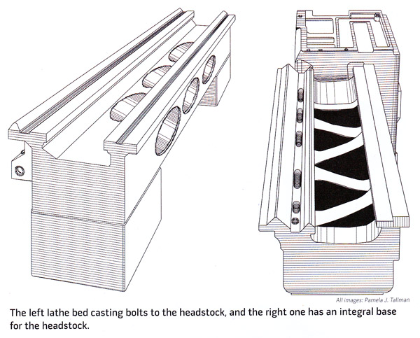
The headstock has several functions. It supports and aligns the spindle and its bearings so the axis of the headstock remains coaxial with the tailstock and parallel to the ways. Like the bed, the headstock structure resists cutting forces acting to force it out of alignment. In most lathe designs, it is permanently and rigidly connected to the lathe bed or part of the same casting. The headstock also contains and supports belts, pulleys and gearing that couple the lathe motor to its spindle and provides a range of spindle speeds. Sometimes the headstock also provides support for the lathe motor.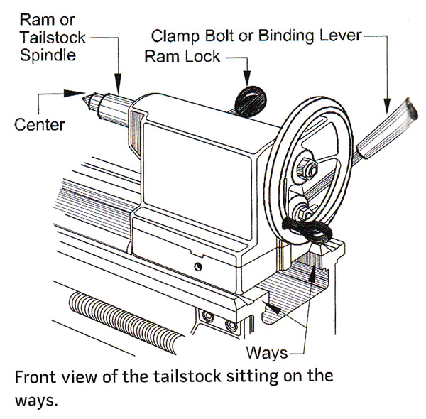
The tailstock is usually a casting that slides along the ways. A locking mechanism called the clamp bolt or binding lever secures it to the ways and prevents it from moving. The tailstock holds a lathe center in its ram for turning or facing. The ram, which is also called the tailstock spindle, is driven in and out of the tailstock casting by a screw thread and handwheel, and locked into position. In addition, the taiistock holds a tool in a chuck or directly in its internal Morse taper. The screw mechanism of the ram forces the tool into the rotating work. The headstock has several functions. It supports and aligns the spindle and its bearings so the axis of the head- stock remains coaxial with the tailstock and parallel to the ways. Like the bed, the headstock structure resists cutting forces acting to force it out of alignment. In most lathe designs, it is permanently and rigidly connected to the lathe bed or part of the same casting. The headstock also contains and supports belts, pulleys and gearing that couple the lathe motor to its spindle and provides a range of spindle speeds. Sometimes the headstock also provides support for the lathe motor.
The tailstock is usually a casting that slides along the ways. A locking mechanism called the clamp bolt or binding lever secures it to the ways and Prevents it from moving. The tailstock holds a lathe center in its ram for turning or facing. The ram, which is also called the tailstock spindle, is driven in and out of the tailstock casting by a screw thread and handwheel, and locked into position. In addition, the tailstock holds a tool in a chuck or directly in its internal Morse taper. The screw mechanism of the ram forces the tool into the rotating work. Although the tailstock barrel is usually concentric with the headstock, most tailstocks can be moved out of this
alignment to cut tapers.
The carriage has four components: saddle, apron, compound slide and cross, or tip, slide. The saddle is the H-shaped casting that rests on the ways. It forms the base of the carriage and supports both the cross slide and apron. The underside of the saddle faces slides along the ways. The apron is the flat, vertical, rectangular plate on the operator's side of the saddle. Inside are the drive mechanisms to move the carriage along the ways using manual or power feed. On lathes with cross feed--the ability to drive the cross slide at right angles to the ways--an additional mechanism inside the apron uses the leadscrew to drive the cross slide. The half-nut mechanism inside the apron locks the carriage to the leadscrew for thread cutting. Controls for power feeds and threading are located on the apron face. The carriage locking screw binds the saddle to the ways, which ensures the calibrations on the compound rest are accurate by preventing saddle movement.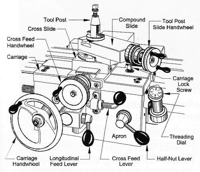
The compound slide holds the tool-holder. On most lathes, the compound slide can be swiveled 360" and locked in any position. This permits the tool to move across the work at any angle by turning the tool post slide handwheel. The compound slide has degree calibrations to simplify setting its angle. The compound slide typically does not have power feed. The cross, or top, slide is a casting on top of the saddle that holds the compound rest. The cross slide moves at right angles to the ways either manually turning the cross-feed handwheel or using the power cross feed.