- Preface
- Acknowledgements
- Chapter 1: Welding Overview
- Chapter 2: Safety
- Chapter 3: Terms, Joints, & Edge Preparation
- Chapter 4: Tools & Welding Tables
- Chapter 5: Shielded Metal Arc Welding
- Chapter 6: Wire Feed Welding
- Chapter 7: Gas Tungsten Arc Welding
- Chapter 8: Oxyacetylene
- Chapter 9: Controlling Distortion
- Chapter 10: Cutting Processes
- Chapter 11: Brazing & Soldering
- Chapter 12: Common Problems & Solutions
- Chapter 13: Design Tips
- Chapter 14: Fabrication & Repair Tips
- Chapter 15: Tools & Tooling
- Chapter 16: Pipe & Tubing
- Chapter 17: Metallurgy
- Chapter 18: Power Supplies & Electrical Safety
- Chapter 19: Bending & Straightening
- Index
- Credits
Chapter 3
Terms, Joints,& Edge Preparation
The more original a discovery,the more obvious it seems afterwards.
Arthur Koestler
Weld Bead Terms
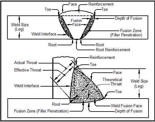
- Parts of the Weld – The two most common welds are the groove and the fillet weld. Figure 3-1 shows the parts of these welds.

Figure 3-1. Parts of a groove weld (top) and a fillet weld (bottom).
- Slag, though technically not part of the weld, is created along with the weld bead. Slag is deposited by the welding electrode to protect the weld metal while it cools. Slag must be completely removed between passes because it will form inclusions within the weld metal and weaken the weld. Slag is usually removed with a slag hammer and a wire brush, and sometimes a wire wheel. Some welders prefer a claw hammer instead of a slag hammer. On pipe welding, grinders and power wheels are used between each welding pass to assure a slag-free surface for the next pass.
Weld Axis & Weld Angles
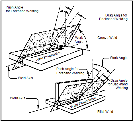
- Weld axis is an imaginary line drawn parallel to the weld bead through the center of the weld. Weld angles are measured from the weld axis.
- Travel angle is the smallest angle formed between the electrode axis and the weld axis. See Figure 3-2 (top).
- Work angle is the angle of less than 90º between a line perpendicular to the major workpiece surface and the plane determined by the electrode axis and the weld axis. See Figure 3-2 (bottom).

Figure 3-2. Travel angle, work angle, push and drag angles for groove and fillet welds.
- Push angle for forehand welding is the travel angle during push welding when the electrode is pointing toward the direction of welding.
- Travel speed is the velocity of the electrode rod or wire as it moves along the travel axis. Travel speed is usually measured in inches per minute.
- Drag angle for backhand welding is the travel angle during welding when the electrode is pointing away from the direction of welding.
Types of Welds
- A stringer bead is a weld which is deposited when the path of the electrode is straight and parallel to the axis of the weld.
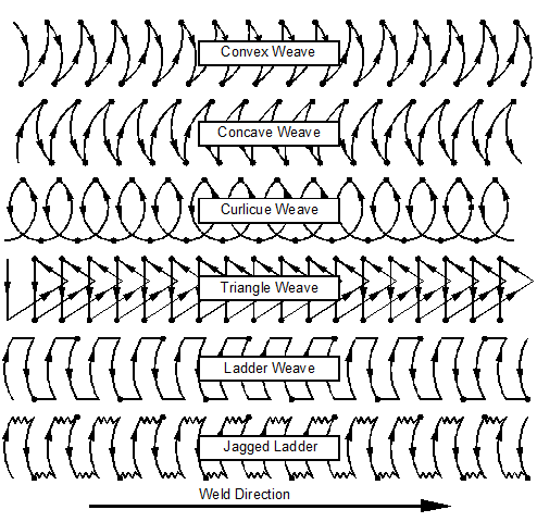
- A weave bead is created when the welding rod or electrode is used in a side-to-side motion to make the weld. See Figure 3-3 for weave bead patterns. Weaving applies heat directly to the edges of the weld puddle. This insures that the puddle fully wets the edges of the joint and reduces the chances of a cold joint. The force of the arc is alternately directed to the sides of the weld because the axis of the electrode points from side to side of the joint as the weaving progresses. This arc-force churns the weld puddle and brings trash to the weld surface, a desirable effect.

Figure 3-3. Weave bead patterns. The dots indicate pause points which apply additional heat and metal
at the edge of the bead where it is most needed.
In general, the width of the weave pattern should not exceed twice the electrode diameter. Weaving makes the weld bead wider and the heat-affected zone larger than that of a stringer bead. Weaving also reduces the height of the weld bead by “spreading it out” which allows the metal to cool more rapidly than if the heat were concentrated in a straight-line stringer bead. If the arc stays in the middle of the weld puddle as it does with stringer beads, all the welding heat has to pass through the molten weld metal before heating the base metal. The spreading out of weave beads is particularly helpful in out-of-position welds where too large a weld puddle can sag due to gravity.
The dots in the weave patterns of Figure 3-3 represent dwell or pause points which applies heat to the edges of the puddle where it is needed. No dwell is needed in the center of the puddle because it is already hot and does not require additional heat input.
Weaving is often used on the final, or cover pass, of a weld. Figure 3-4 shows how the cover pass weld bead on a pipe weld can be widened to stretch completely across the joint.

Figure 3-4. The four passes needed to complete this welded pipe joint. The cover pass is a weave bead.
More on pipe welding in Chapter 16 – Pipe & Tubing.
Some weaving applications are:
- Single-pass welding – A weave bead can be used to complete a joint with a single pass when the available electrode is too small to deposit enough filler metal in a single pass with a stringer bead. This may occur because the available welding power supply is too small to run a large electrode that would make the bead in a single pass, and several passes with a smaller rod or electrode would be needed. On SMAW, weaving not only increases the width of the filler metal deposit, weaving decreases overlap, and assists in slag formation.
- Open root-pass welding – Weaving is necessary to draw the weld puddle onto both sides of the open root and apply enough heat for complete fusion or “wetting.”

