- Acknowledgements
- Introduction
- Chapter 1: Measurement Tools, Layout & Job Planning
- Chapter 2: Basic Hand Tools
- Chapter 3: Filing & Sawing
- Chapter 4: Grinding, Reaming, Broaching & Lapping
- Chapter 5: Drills & Drilling Operations
- Chapter 6: Threads & Threading
- Chapter 7: Turning Operations
- Chapter 8: Milling Operations
- Chapter 9: Fastening Methods
- Chapter 10: Why Steel Hardens
- Chapter 11: Safety & Good Shop Practices
- Chapter 12: Other Shop Know-how
- Appendix I: Sharpening Steel Lathe Tools
- Appendix II: Surface Speed Table & Cutting Tool Selector Chart
- Appendix III: Decimal Equivalents of Fractional, Letter & Metric Drills
- Glossary
- Index
Chapter 5
Drills & Drilling Operations
Procrastination is the thief of time.
—Edward Young
Introduction
Drilling holes is the most common of all machining processes, and the tool most commonly used to make them is the twist drill. Twist drills remove metal from holes and reduce it to chips in a fast, simple, and economical process. Nearly 75% of the metal removed by machining is drilled out. Drilling is often the starting point for other operations such as reaming, counterboring, countersinking, and tapping. Though usually used in a drill press, also called a drilling machine, twist drills can be used in lathes and milling machines. There are many twist drill designs. Some optimize drilling speed, diameter control, and wall smoothness, while others perform deep-hole drilling or drill very hard materials. This chapter covers the designs most useful to non-production, small- and medium sized shops.
The most popular drill press design is the sensitive drill press. We’ll cover two sizes of this machine using current commercial models. Also, we’ll examine how drill press size is measured, drill press components and controls, twist drill sizing systems, the mechanics of drilling, securing work, and drill speeds and feeds. Procedures for transferring hole position, correcting off-position drills, extending drills for a longer reach, the use of bushings, and the making of drilling jigs are included. In addition, this chapter looks at other, non-twist drill designs, such as flycutters and punches. Although drilling metal is our primary interest, the drilling of wood, plastic, glass, and rubber is also covered. Two other hole-related procedures, reaming and tapping, are covered in Chapter 4 – Grinding, Reaming, Broaching & Lapping, and in Chapter 6 – Threads & Threading, respectively.
Section I – Drill Presses
Specifying Drill Press Size
What are six common ways of specifying the capacity of a drill press?
- Maximum throat depth, the distance between the spindle center and the drill column. This measurement indicates how far the drill press can place a hole from the edge of a workpiece. This depth is also the radius of the largest circle whose center can be drilled.
- Maximum hole diameter, the largest hole which can be made in steel and in cast iron using twist drills based on available speed and motor torque.
- Spindle travel, the maximum tool stroke that can be taken without repositioning the table. It indicates the deepest hole easily drilled.
- Maximum vertical clearance, the distance between the end of the chuck and the worktable.
- Range of spindle speeds.
- Motor horsepower.
All six parameters are needed to characterize a drilling machine.
Small & Medium Drilling Machines
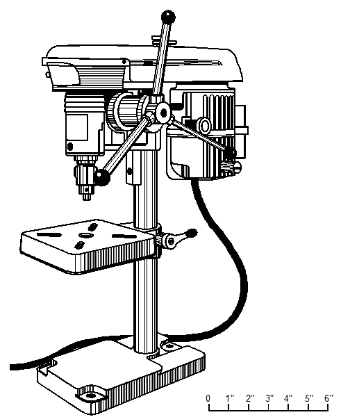
- Cameron Series 164 miniature drill press, Figure 5–1, has a single-speed motor and delivers three spindle speeds of 9500, 17,000, and 30,000 rpm via stepped pulleys. It has a rack and pinion feed, and drills holes from 0.002- to 0.150-inches diameter to the center of a 5-inch circle. Spindle runout at the chuck mounting taper is less than 0.0001 inches. Spindles, pulleys, and motors are dynamically balanced for smooth operation. A clear plastic cover allows viewing of the belt and pulley positions. The 434-inch worktable is slotted and has a ⅝-inch center hole. Some of the available options are: variable speed controls, foot operated speed controls, two-speed motors to provide 6 spindle speeds of 7500, 9500, 14,000, 17,000, 24,000, and 30,000 rpm, and Jacobs key-type chucks or Albrecht precision keyless chucks. Dial indicators to determine hole depth are available, too. Motors are 240/120 VAC at 2.5/5 A. These drill presses are manufactured by Cameron Micro Drill Presses, a Division of Treat Enterprises in Sonora, California 95370.

Figure 5–1. Cameron Series 164 miniature drill press.
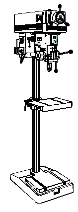
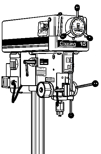
- Clausing 15-inch floor drill press, Figure 5–2, is a medium-heavy industrial-grade machine suitable for production work, a general machine shop, or an industrial prototype lab. It has a maximum throat depth of 15 inches and can drill a ⅝-inch hole in mild steel or cast iron. The maximum spindle-to-table distance is 41 inches and maximum spindle-to-base distance is 47 inches. Its tilting table is 14310 inches and its base is 13310 inches. The 3-inch diameter ground steel vertical column is 3/16-inches thick for rigidity. The 2-inch diameter quill is ground steel. All models include a micrometer depth stop and a push button safety switch. There are also two choices of infinitely variable speed units (330/2460 rpm and 500/4000 rpm) and two five-speed step-pulley models (260/3600 rpm and 400/5400 rpm). In addition, there is a choice between a ½-inch capacity key chuck and a #2 Morse taper spindle. An optional air-hydraulic feed is available for production work. Both single-phase 115/230 volt, 60 Hz motors and three-phase 208/220/440 volt, 60 Hz ball-bearing, ¾-horsepower motors are available. Overall dimensions are 72.6 (H)315.5 (W)328 (D) inches. This drill press weights 300 pounds. Clausing Industrial, Inc. makes it in Kalamazoo, Michigan 49007.


Figure 5–2. Clausing 15-inch floor drill press.
Drill Press Components & Controls
What are the major components of a drill press?
There are four major components of a drill press: the base, the column, the head, and the quill assembly. The base and column are usually of cast iron or steel, and they support all the other components. The head, typically a large casting, contains the motor, drive belts, speed changing mechanism, and the quill assembly. The head fits on the top of the column, and the quill assembly inside the head holds the spindle and the chuck.
What are the typical controls and adjustments on a drill press?
- Power switch.
- Downfeed handle, controls chuck position and can exert considerable force on the drill to maintain cutting action.
- Quill lock, secures the chuck at any point in its travel range. It is used when the drill press performs light buffing, grinding or milling.
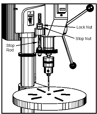
- Depth stop, Figure 5–3, controls hole depth by limiting quill travel with a mechanical stop. Adjusting the stop nut position along a threaded rod controls depth, and the lock nut secures the stop nut from vibration.

Figure 5–3. Parts of a drill press depth stop.

