
Thread History and Measurement
Publication:Screw threads were used in the time of Plato, about 500 B.C., in grape and olive presses. About 100 years later, Archimedes was credited with inventing a water pump based on the screw to irrigate crops and remove water from ship bilges. Later, the Romans used this pump to dewater mines.
Until Jesse Ramsden, an English instrument maker, developed the first satisfactory screw-cutting lathe in 1770, all screw threads were cut by hand. This limited most threads to large wooden ones for presses and clamps until 1800 until Henry Maudslay, a machinist, produced a large screw-cutting lathe.
The development of steam engines, trains and machine tools created demand for threads in the form of nuts, bolts and lead screws. But lack of standardization was a great obstacle to the widespread use of threaded fasteners. Each workshop had its own fastener designs and they were not interchangeable.
To overcome these problems, Joseph Whitworth collected sample screws from a large number of British workshops, and in 1841 proposed that the thread angle be standardized at 55° and that the number of threads per inch should be standardized for various diameters. His proposals became standard practice in Britain in the 1860s.
In 1864, William Sellers, an engineer and machine tool builder in Pennsylvania, independently proposed another standard based on a 60° thread and set thread
pitches for different diameters. This was adopted as the U.S. Standard and subsequently developed into the American Standard Coarse Series (NC) and the Fine Series (NF). In continental Europe, several different thread standards emerged, but German and French standards based on the metric system and a 60° thread prevailed, and metric threads were established.
Today, threads are used to actuate other mechanical components, such as wind flaps on aircraft, measure distance as micrometer threads, adjust and hold length as tie rods and turnbuckles, and fasten, as with nuts and bolts.
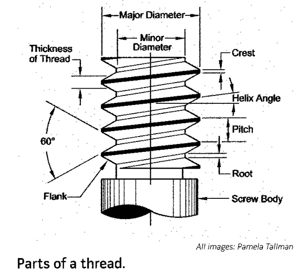
The basic parts of a thread are the major diameter (the outer or largest diameter), minor diameter (the smallest diameter), pitch (the distance between adjoining threads) and form (the profile or shape of a thread).
Parts of a Thread
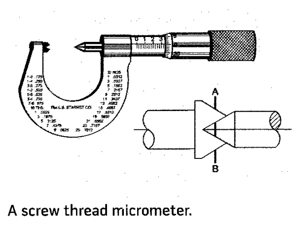
One is a screw thread micrometer, which differs from a regular micrometer in having a cone-shaped spindle and a mating anvil. These fit over threads and measure a thread's major diameter less the depth of one thread. This method works well for threading operations because the work does not have to be removed from the lathe to take the measurement.
Screw Thread Micrometer
The three-wire method uses a regular micrometer placed over three same-size wires of a specific diameter for the thread being measured. Entering the thread dimensions into the following formula yields the diameter over the wires for a full-depth 60° American National Thread. This method works well for lathe threading operations because it can be done while the work remains in the lathe.
Three Wire Method
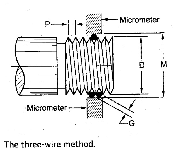
The formula is M=D + 3G - (1.5155/N), where M is the measurement over the wires, D is the thread's major diameter, G is the diameter of the wires, P is pitch (1/N) and N is the number of threads per inch (tpi).
The largest wire size is 1.010/N = 1.010 P.
The best wire size is 0.577351N = 0.57735 P.
The smallest wire size is 0.505/N = 0.505 P.
Note that G must be no larger or no smaller than the sizes shown above. Any wire between the largest and smallest may be used. All wires must be the same size.
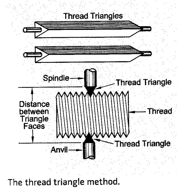
The thread triangle method measures the distance over a pair of steel triangles between the thread roots. A reference chart is then used to determine thread depth. This measuring method also works well for lathe threading while the work remains in the lathe.
Thread Triangle Method
 .
.
Thread ring gages and plug gages are commercial master thread gages for external and internal threads. These are highly accurate and often used in pairs of GO and NO-GO dimensions. Work must be removed from the lathe to measure external threads between centers.
An optical comparator, which projects a magnified shadowgraph of the part on a ground glass screen, is useful to determine a thread's shape and dimensions, but not useful for checking work while it is in the lathe. These are also useful for checking a cutting tool’s shape.
Using the mating part itself is often the best choice for checking threads, particularly in nonproduction or spare parts situations.
Not all measurement methods work for all types of threads. For example, internal and tapered threads cannot be checked with a thread micrometer or with the three-wire method, but a plug gage will work fine.