- Title Page
- Copyright Page
- Contents
- Preface
- Acknowledgements
- Chapter 1: Setting Up Shop
- Chapter 2: Metals, Alloys, Oils & Hardness Testing
- Chapter 3: Tapers, Dowel Pins, Fasteners & Key Concepts
- Chapter 4: Filing & Grinding
- Chapter 5: Drilling, Reaming & Tapping
- Chapter 6: Bandsaws
- Chapter 7: Lathes
- Chapter 8: Milling Machines
- Chapter 9: Machine Shop Know How
- Index
- Credits
Chapter 5
Drilling, Reaming & Tapping
Every discovery contains an irrational element of creative intuition.
—Karl Popper
Section I – Drills
Introduction
Drilling holes is the most common of all machining processes—nearly 75% of the metal removed by machining is drilled out, usually using twist drills. Drills remove metal by reducing it to chips in a fast, simple and economical process. Used in drill presses, lathes and milling machines, twist drills are among the least expensive and most versatile cutting tools. The fact that most industrial tool distributors place twist drills at the very front of their catalogs is testimony to the drill’s importance and popularity. This chapter concentrates on twist drills, but also examines several other drill designs.
Twist Drill Development
Until the US Civil War, most holes in cast iron and steel were drilled using a forged spade-shaped drill on the end of a square or round steel shaft. See the spade drill in Figure 5-1. Because these spade drills had no way to remove chips from the drilled hole, peck drilling was required—making drilling a slow, laborious process. These early drills were carbon steel and annealed easily, so drill spindle speeds had to be kept low to prevent the drills from overheating and becoming annealed. Then in 1861, Stephen A. Morse of Massachusetts invented the twist drill.
Twist drills got their name because they were originally made by milling straight flutes into steel rounds, which were then heated red-hot and twisted to form helical flutes. Although a few twist drills are still made this way, today most twist drills are made by grinding helical flutes into solid rounds.
Figure 5-1. Typical spade drill design from about 1855.
The twist drill was a big improvement over the spade drills of the 1850s and 1860s because their helical drill flutes pulled chips out of the drill hole and reduced the need for peck drilling. But it wasn’t until about 1900, when HSS—with its superior high temperature strength and wear resistance—became available, did the twist drill design demonstrate its superiority and become widely adopted. The term high-speed steel indicates that, unlike carbon steel cutting tools, HSS cutting tools can be run at high speeds without becoming annealed.
A number of doctoral candidates have done dissertations on twist drills, studying them in depth. Their conclusions are that, despite the drill’s apparent simplicity, it is a complex device and very difficult to model mathematically. Over the last 160 years, however, many excellent twist drill designs have been developed by systematically experimenting with different shapes and materials, observing their performance, and choosing the most effective designs. Because of their economic impact on today’s manufacturing, research continues on twist drills aimed at minimizing axial force and torque, and maximizing drill life. Even small improvements in drilling can have a huge financial impact because so much machining activity involves drilling. The most recent important developments, which have greatly increased drill life—especially in a production setting—are the addition of thin, hard, wear-resistant coatings including titanium nitride, zirconium nitride, titanium carbo-nitride, titanium aluminum nitride, chrome nitride, amorphous diamond and polycrystalline diamond.
Throughout history, most successful inventions show major design changes as they are improved over time, but not so with the twist drill. The illustration of Stephen A. Morse’s original 1863 US twist drill patent, as seen in Figure 5-2, shows how closely today’s twist drills follow the inventor’s original design.
|
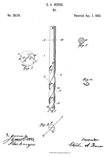
Figure 5-2. Stephen A. Morse’s original twist drill patent from 1863.
Section II – Anatomy of the Twist Drill
The most common and basic twist drill is called the conventional 118º twist drill, or general-purpose drill. Because of its importance in the machine shop, Section II will concentrate on this drill.
The Shank
The twist drill shank, which fits into the drilling machine spindle, holds the drill in position and transmits the driving torque to the drill. Many shanks are straight and the same diameter as the nominal drill size. These shanks fit into drill chucks or collets. Other drills, usually ½-inch diameter and larger, have a Morse taper shank. Some HSS Cobalt drills have a small step on the end of the shank to differentiate them from the less expensive HSS drills. Because drills are held by the upper end of their shanks during manufacturing heat treatment, shanks tend to be much softer than the flute and point areas. See the hardness zones in Figure 5-3 (bottom). This softer area makes it easier to turn down a drill shank in the lathe, if needed, to fit into a smaller chuck.
The Body
The drill body, the section from the heel to the point, contains the flutes—helical grooves ground into the side of the drill to evacuate the drilling chips. The portions of the drill body not ground away to form the flutes are called the lands.
At the bottom of the flutes lies an invisible solid cone of drill steel called the drill web, or web core, which gives the drill its stiffness. The web core is usually 20–30% of the drill diameter, and is often tapered wider at the shank end to provide more stiffness and shallower at the point end to provide more room for chip clearance. See Figure 5-3 (top).
Figure 5-3. The web lies inside the drill (top) and drill hardness zones (bottom).
To reduce friction between the lands of the drill and the wall of the hole being drilled, the lands are relieved so that just a small helical strip, the margin of the land, is the full drill diameter. On a ¾-inch drill, the lands would typically be about 0.015 inches below the margins of the lands.
To further reduce friction, the drill body is usually reduced several thousandths of an inch from the point to the start of the shank. This reduction in diameter—really on the outer edge of the margins of the lands—is called back taper, and is typically 0.0005–0.00075 inches/inch of drill length.
Most twist drills are a compromise between a large flute space for chip removal and a heavy web thickness for drill rigidity. There are some drills, though, with extra-thick webs for applications where heavy axial force will be applied.
Helix Angle
Figure 5-4 shows the helix angle, which measures the twist of the drill flutes. Most twist drills have about a 30º helix angle, called the standard helix. This standard helix angle optimizes chip ejection, drill cross-sectional strength and drill rigidity. High helix drills, also called fast spiral angle drills, have a 40º helix. They are used for high feed rates under low spindle speeds usually on softer non-ferrous metals like aluminum, magnesium, zinc die castings, brass in deep holes and some plastics. In general, the deeper the hole, the higher the helix angle should be for chip removal. Low helix drills, or slow spiral angle drills, typically have about a 12º helix. They are used with high spindle speeds on hard-to-drill materials. These low helix drills have increased cutting edge strength and work well on materials with a tendency to gall or clog the drill hole. In a non-production setting, though, the standard helix angle is satisfactory for nearly every drilling task.
Figure 5-4. The drill helix angle and drill point angle.
The Drill Point & Point Angle
The drill point is geometrically complex. It is formed from the flanks, which are the ends of the lands at the drill point, and from the chisel point, which is formed by the end of the web when it reaches the point. The cutting edges of the flanks are called the lips, or the cutting lips. The sharpening of the drill during manufacturing creates the chisel point.
Although a twist drill can be ground to any point angle, the four common point angles in use today meet most drilling requirements. See Figure 5-5.
Figure 5-5. These are the four most common drill point angles.
Rake Angle
The rake angle is where the cutting lips and the flute faces meet to form the drill’s cutting edges. Because the rake angle changes continuously across the lips—usually from a positive rake at the outside corner to a negative rake where the lips meet the chisel edge—the term effective rake angle is often used to take into account the continuous changes in the cutting edge angle across the lips. The effective rake angle is a kind of average angle that reflects the total effect of these angular changes. This angle cannot be measured as it changes continuously along the drill’s cutting edge. It can only be calculated.
The nominal rake angle is more easily defined, visualized and measured. Figure 5-6 shows the nominal rake angle. For our purposes, this angle provides an adequate measure to see how the rake angle affects drill performance. The nominal rake angle determines:
- Sharpness of the lips and how the cutting edge gets under, or enters, the workpiece material and cuts it. Harder materials require a smaller rake angle—a sharper lip—than softer materials.